Data Blocks in Simatic Step 7 Siemens :

Data Blocks (DBs) can be used by your program to save data in the CPU. Your hard disk contains up to 8 Kbytes(8192Bytes) space. There are two types of data blocks. Global DBs, where all OBs, FBs and FCs read all saved data or can even write in the DB and local instance DBs, which are assigned a particular FB. In the DBs, different data types (e.g. BOOL or WORD) can be saved in arbitrary order. This structuring of a DB follows through input in a table with the tool LAD, STL, FBD - S7 Block Programming.
In the program structure from STEP 7, data blocks are found as follows:
Data blocks are generated and opened like program blocks in the tool LAD, STL, FBD: Programblocks. They serve e.g. for the saving of data and system states.
In the program structure from STEP 7, data blocks are found as follows:
Data blocks are generated and opened like program blocks in the tool LAD, STL, FBD: Programblocks. They serve e.g. for the saving of data and system states.

Before create Data Blocks (DBs), we must understand about addressing Data in Simatic Step7. Figure 2 show the addressing data elements in Simatic Step7. There is 3 elementary data type:
- Bit data Type (Bool, Byte, Word, DWord, Char)
- Mathematical data type (Int, Dint, Real)
- Time types (s5Time, Time, Date, Time_of_Day)
HOW TO GENERATE DATA BLOCKS (DBS) IN SIMATIC S7-PLCSIM
STEP 1: CREATE NEW PROJECT
Follow Step 1 to Step 3 of the article about Learning PLC Programming With SIMATIC S7-PLCSIMStart from Step 1: Setup PG/PC Interface, Step 2: Create New Project and Step 3: Add Station Object
STEP 2: INSERT S7 PROGRAM
Insert a new S7-Program, in INSERT menu select PROGRAM and then S7 PROGRAM |
| Figure 3 Insert S7 program |
STEP 3: INSERT DATA BLOCK
Highlight the folder Block |
| Figure 4 Folder Block |
Insert Data Block, in INSERT menu select S7 Block and then Data Block
 |
| Figure 5 Insert Data Block |
Enter the number for Data Block in Name and type (in this case I set DB1), choose Shared DB so DB can accessed by another program. For Symbolic Name and Symbolic Comment is optional. Accept with OK
 |
| Figure 6 Data Block |
STEP 4: CREATE DATA VARIABLE
Open the data block DB1 with double click or open object. |
| Figure 7 Data Block DB1 |
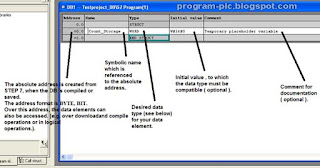
The Data Block is generated with a symbol Name. The Type, an Initial value as well as aComment (optional) are entered.The address is automatically generated and cannot be altered. In Data
 |
| Figure 8 Program Block for Data Block |
Fill the Data Block like figure below, Click save for save all changes.
 |
| Figure 9 Data Block |
STEP 5: STORE DATA INTO DATA BLOCK
Now we create program to write data to Data Block, in simatic manager double click on OB1. When Properties – Organization Block Window open choose LAD in Created in Language. Click OK.
 |
| Figure 11 Organization Block Properties |
Expand folder counter in library, select S_CU function and drag to, main window.
 |
| Figure 12 Insert S_CU Function |
 |
| Figure 13 Insert S_CU Function |
Function Description
In this case, we will not use all parameter in S_Cu Function. We only use Input counter CU and Counter Value CV for store data in DB1. Create program like figure below

STEP 6: SIMULATION
Save and close program object window. Run PLCSim with click on PLCSim icon. |
| Figure 15 PLCSim |
And create input output variable for IB 0 (Input), C 0 (Counter), and DB1.DBW0 (Data Block).
 |
| Figure 16 PLCSim ON |
Download program
 |
| Figure 17 Download Program |
Run simulation
 |
| Figure 18 Run Simulation |
 |
| Figure 19 Simulation Store data in DB |
Set IB 0.0 to 1, and see counter in C 0 count 1 and counter store data into DB1.DBW0. Set IB 0.0 to 0 and repeat set IB 0.0 to 1 again, see the count in counter increase and store to DB1.DBW0.
STEP 7: DATA VIEW MODE IN DATA BLOCK
Double click on DB1 in Simatic manager, to open DB1 editor |
| Figure 20 Open DB1 |
In VIEW menu select Data View,
 |
| Figure 21 Data View |
Select Monitor mode
 |
| Figure 22 Monitor mode |
And check data in DB1 in PLCSim and Program Object Data Block, it must be same.
 |
| Figure 23 Data Block Monitor |
No comments:
Post a Comment